-40%
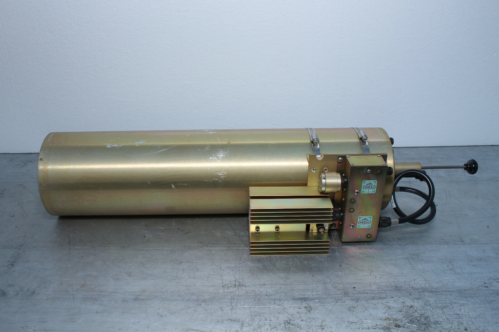
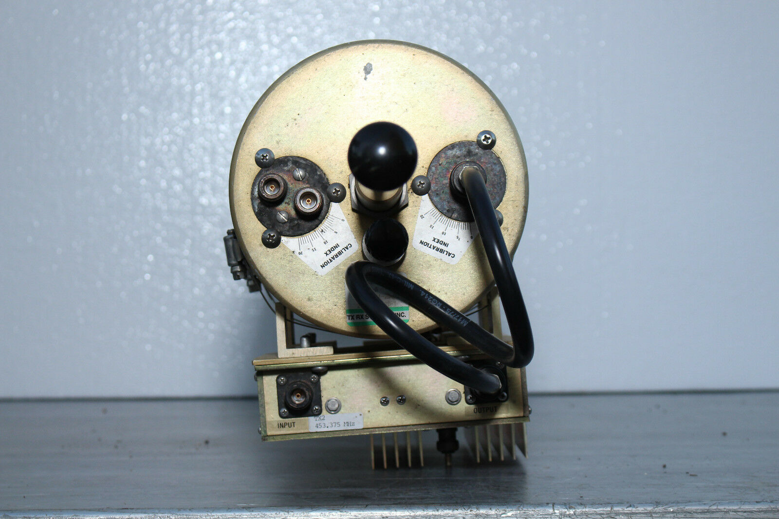
TX/RX 73-67-11-2d-02 T-Pass Combiner w/ 21-70-11-2d-t Expansion 5-100 Watt
$ 1056
- Description
- Size Guide
Description
TX/RX 73-67-11-2d-02 T-Pass Combiner w/ 21-70-11-2d-t Expansion 5-100 WattThis sale is for a TX/RX 73-67-11-2d-02 T-Pass Combiner w/ 21-70-11-2d-t Expansion 5-100 Watt
Configuration:
73-67-11-2d-02 Combiner,406‐512MHz,T‐Pass, Tx, 2 Channel, 6" Diameter 3/4 Wave Cavity,5W/100W
with
21-70-11-2d-t 450-470 MHz T-Pass expansion Channel,450‐470 MHz,T Pass, Tx,6" Diameter 3/4 Wave Cavity,5W‐100W,RF Sampler Tap
Condition:
Excellent condition, fully functional.
Warranty:
30 Day Warranty.
We pledge to offer the best service and warranty to all of our customers! We are extending a 30 day warranty on this item. This is our way of saying thank you for allowing us to serve you.
Certification:
This is an genuine product from this manufacturer.
Web Information:
product specifications:
Item No
73-67-11 Series
Item Name
406-512 MHz, T-Pass Combiner, 6.625” Cavity
Frequency Range
406-512 MHz
Cavity Type and Diameter
3/4-wave, 6.625” (168 mm)
Maximum Continuous Transmit Power
150 W
Isolator Load Pwr Continuous
73-67-11-2B-nn:
5 W/25 W [Note 3]
73-67-11-2D-nn:
5 W/100 W
Min Tx-Tx Separation at Cavity Loss
215 kHz @ -1.5 dB
115 kHz @ -2.5 dB
Typical Tx-Tx Isolation at Min Separation
Typical Antenna - Tx Isolation
Typical Tx Noise Suppression
Depends on cavity loss
Impedance Ω
50
Maximum Input Return Loss - VSWR
-20 dB (1.22:1)
Temperature Range
-30 to +60 °C
Connectors - Input and Antenna
N
Mounting
Peg Rack®
Mounting Options
MC:19" rackmount adapter plates, 17.5" high
LR: System supplied without Peg Rack® [Notes 4,5]
21-70-11-xx-T Series
21-70-11-xx-T Series, 450-470 MHz T-Pass Expansion Channel
assemblies consist of the following items:
A 6.625" 3-quarterwave T-Pass® cavity filter
A dual ferrite isolator, with RF loads and coaxial cable for connection to the cavity
An RF sampler to measure RF power reflected into the isolator output load
Isolator and channel mounting hardware
Expansion assemblies for channel 2 and higher are supplied with a thruline of the correct length for the new channel frequency.
Starter channels (channel 1, bottom) are supplied with a short circuit on the T-Pass loop.
Ordering Information
To order an expansion channel, specify the following:
Frequency and position of all channels in the system to be expanded
New channel frequencies
Transmitter output power on all new channels
T-Pass® Expansion Channel Guide
